Java Applet for Mortar Fire Control
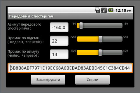
Direct Fire: Anybody who has been following events in Libya, Syria, Yemen, etc. knows that, in rebel-held towns, the roofs of tall office buildings are often the only ground the government forces hold. It is good ground for snipers (because they have helicopters; if you were up there, they would just machine gun you) but, typically, it is impractical to position guns up there because the roof is not strong enough and/or the helicopters are not big enough. Example: Suppose that snipers armed with OSV-94 12.7 mm rifles are shooting demonstrators in the square below from the roof of a municipal building 100 m tall on level ground. The altitude is 1400 m, the temperature is 15°C and standard air pressure. From 1200 m away, to avoid the OSV-94s, you are firing shells at 150 m/s that are ballistically equivalent to 73.6 mm steel balls. There is a 10 m/s wind from 4 o’clock. If your mortar is mounted in the bed of a pickup so the muzzle is 2 m above ground, then you should input the muzzle height as -98 m because the building is 100 m high. By inputting several trial angles of elevation, one can quickly find that 64.6° results in a range of 1200.6 m. The windage correction is 39.7 mils right.
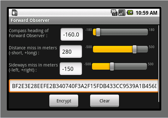
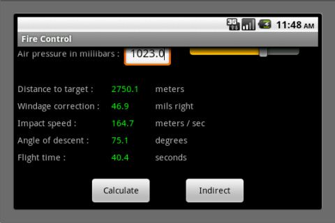
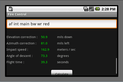
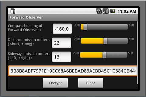
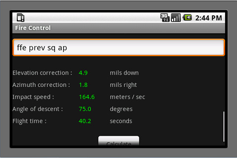
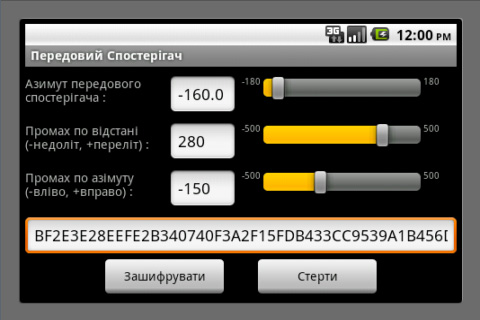
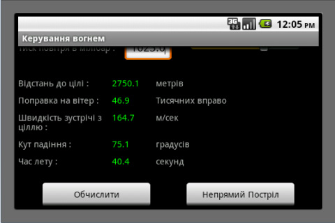
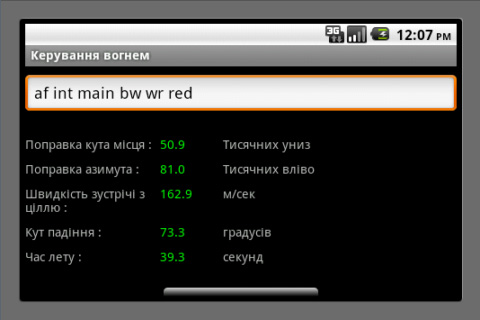
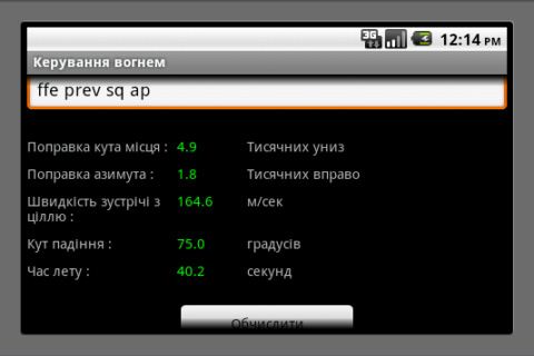
Proposal for a Weapon to Target the Rooftops of Skyscrapers Indirect Fire: Suppose that you are in a trench with your muzzle 5 m below ground level. The enemy is on a hill with a 7% grade and concealed in a grove of trees. The altitude is 1400 m, the temperature is 15°C and standard air pressure. You are firing shells at 350 m/s that are ballistically equivalent to 73.6 mm steel balls. You have previously determined that, if you fire at 57° off magnetic north at an angle of elevation of 60° in no wind, you will hit a certain building 1300.4 m away. There is now a 10 m/s wind from 4 o’clock when facing 57° off magnetic north. Input this data along with the current wind into the direct-fire program to determine that the wind requires an angle of elevation of 61.4° and 35.6 mils right azimuth correction. Go to the indirect-fire program and observe that this data has been automatically transferred. The 35.6 mills right windage correction has been converted to 2.0° right but you must manually add the 57° to get 59°. Your forward observer (FO), who sees the enemy at -172° off magnetic north, reports that this building is 139 m past the target and 84 m to the left. Input this data, hit “calculate” and you will be advised to adjust your angle of elevation 60.2 mils down and your azimuth angle 106.2 mils left. If you make these corrections off the imaginary shot you just fired at the building, you should hit the enemy or come very close with your first shot. Note that you and your FO are both reading your compasses in degrees off magnetic north, without regard for declination. This is because the software only cares about the difference between your compass readings and is not trying to locate the target on a map that is oriented towards true north. Also note that, in this example, the FO is on the other side of the target. It is not his job to mentally rotate the coordinate system to determine whether you see the miss as being on the left or the right. He just reports what he sees from his own perspective. Indeed, he does not need to know where you are and probably should not in the event that he is captured and the enemy demands this information of him. Also note that, if you are receiving meteorological reports with wind speed in knots, you can get meters per second by dividing by two. Click here for a PDF file with instructions for the Android Application and an example where one uses both the direct- and indirect-fire versions to reference off a street intersection that the gunner has not previously test-fired his mortar on. Click here for a PDF file with an explanation of the abbreviations used by the forward observer. The Android Application is just like the Applet above except that it works on Android phones and has a provision for encrypting the FO’s messages using AES encryption. Click here for a summary of the mathematics involved. Targeting: The vehicle most dangerous to snipers and the only one that can be disabled by nearby mortar hits is the ZSU-23-4 (Shilka). This self-propelled anti-aircraft gun can elevate its four 23mm autocannons to 85°, which makes it very dangerous to snipers in tall buildings. Fortunately, it is quite thin-skinned and can be destroyed by direct hits from even light mortars while the water jackets on its autocannons can be damaged by nearby hits. It has a six-power optical sight with no night vision capability or any means of triangulating on rifle shots, so white phosphorous will temporarily blind it. The BMP-3, which carries seven passengers and can raise its gun to 60° is also dangerous, but it is much more difficult to destroy or damage with mortars. Thus, one should concentrate on the Shilkas. A battalion on the attack will typically have two pairs of Shilkas, the vehicles in each pair separated by 200m, and all of them 400m to 500m behind the tanks, though they may be brought forward if the tanks are coming under heavy rocket fire from buildings too tall for the tanks to elevate their guns to. Be aware that tanks have FLIR so, even if they cannot raise their gun enough to shoot snipers and ATGW teams in tall buildings, they can spot for the Shilkas. On defense, the Shilkas will be 1000m to 1500m behind the supported battalions, though they may be brought forward if helicopters are known to be approaching. A battalion on road march will have tanks, then a pair of Shilkas, more armor, another pair of Shilkas and then more armor. In general, Shilkas will always operate in pairs, though keeping 200m apart, and there will be two such pairs per battalion. Good luck! This program uses an iterative method, so drag is indeed proportional to the square of velocity. This assumption is valid for velocities up to 240 m/s. From 240 m/s to 295 m/s, drag is proportional to velocity cubed. From 295 m/s to 375 m/s, drag is proportional to velocity to the fifth power. A lot of software packages say this but, in the fine print, they add that they are going to “make some simplifying assumptions” or “drop the higher order terms.” Then they proceed to solve the much simpler case of drag being directly proportional to velocity. A word to the wise: If drag is proportional to the square (or some higher power) of velocity, range can only be determined by an iterative method. If they are using table look-up (as I did in my pumpkin program) then they are rounding the results off in a way that is only acceptable for vegetables, not steel balls. If they have a formula in closed form – not a DO/UNTIL loop – then they are assuming that drag is proportional to velocity, which is dishonest unless they made that assumption clear. Note. Air density is re-calculated at each step so, if the ball flies so high that the air is significantly thinner at its apex, this is taken into consideration. The coefficient of drag is also re-calculated at every step so it increases from 0.2 to 0.45 at the exact moment that the velocity falls below the critical point. Altitude, air pressure and temperature are all taken into consideration. Note that, so the isobars on weather maps are all in the same units, barometers are usually normalized to what they would read at sea level. This is also what you want because, since altitude is a separate parameter, if you reported the actual number of inches of mercury at your location, you would be over-estimating the effects of altitude. Note that humidity is not taken into consideration. This is because it is negligible – really. Rifle matches are rarely called on account of rain and I can remember lying at the shooting line amusing myself by using my amplified earmuffs to listen to my competitor and his coach earnestly debating, like Twiddledee and Twiddledum, whether they should add one or two minutes of angle to their elevation dial to account for the “heavy, humid air.” This is foolish because humidity has a negligible effect at 600 yards and, anyway, they have got it backwards. Humid air is less dense than dry air. Clouds float, don’t they? Ball bearings are assigned a grade to denote smoothness, starting at about 50 for “precision” bearings, 100 to 500 for “semi-precision” bearings and on up to 2000 or, in some cases, 5000. A polished surface is a mixed blessing. It lowers the coefficient of drag slightly, which increases range. But it also raises the critical point where, when velocity falls below it, there is a dramatic increase in drag. Thus, for balls launched at such great velocities that they stay well over their critical point, smoothness increases range. For balls launched at velocities only slightly above the critical point, smoothness reduces range. This is why golf balls have dimples; because they are driven at velocities near what the critical point would be for smooth balls. For most people, this discussion is academic because they could not afford to launch pricey precision bearings into a lake anyway, even if it were unequivocally a good thing. Bottom line: Buy bearings with a grade of 2000ish and don’t sweat it. A three-inch chrome steel ball is available from Craig Ball Sales for $35. Steel pipe is available from Online Metals in a variety of sizes. For the three-inch ball I would recommend a Schedule 40 nominal 3" pipe with an actual inside diameter of 3.068". The length of mortars is typically less than 15 times their bore diameter, so three feet at $97.70 should be sufficient. Work up a powder charge firing it into a ballistic pendulum until you get 360 m/s. A 1.819 kilogram ball traveling 360 m/s will lift a 150 kilogram pendulum one meter, so build accordingly. This software is intended for use with steel ball bearings, but it can be adapted for other projectiles. Iron Shot and Shells: The iron used in 19th century shot had a specific gravity of about 7.14. Steel has a specific gravity of 7.85, so a steel ball with 91% of the diameter of an iron ball is ballistically equivalent to it. For shells, look up the weight (including the powder; relics are typically weighed with their cavity empty) and the diameter. Convert pounds to kilos (multiply by .4536) and inches to meters (multiply by .0254) and then find the ballistic coefficient by dividing the mass by the square of the diameter and multiplying by 5. Multiply this by 0.04866 to get the diameter in millimeters of a ballistically equivalent steel ball. For example, the 12-pounder howitzer used during the Civil War fired a shell measuring 4.52” and weighing 8.9 pounds, making it ballistically equivalent to a 74.5 mm steel ball. Unstabilized Cylinders: The Stokes Mortar, widely used during World War One and the first mass-produced mortar in history, launched an unstabilized cylinder. The homemade mortar designed by Ragnar Benson is a knock-off of the Stokes Mortar. The ballistic coefficient is between 0.87 and 1.22 times the mass divided by the cross-sectional area. The longer the cylinder is, the higher its ballistic coefficient. Multiply this by 0.04866 to get the diameter of an equivalent steel ball. Of course, once the cylinder starts to tumble, then any further prediction of its trajectory is thrown to the wind – literally. Benson's design would benefit from fins on the small pipe that houses the shotgun cartridge and by a brass rod extending out from the nose to get the center of gravity ahead of the center of pressure. Modern Mortar Shells: Spheres are just pushed sideways by the wind while projectiles with fins may turn their nose into the wind if the fins are too big. This makes windage adjustment vastly more complicated than it is for spheres. Also, such projectiles typically go high enough that the wind is stronger at their apex. Small commercial mortars such as the 60 mm and the 81 mm with initial speeds less than 375 m/s can be modeled by the Java Applet above by finding the diameter of ball that is ballistically equivalent to the shell being used, though one should restrict oneself to relatively mild wind conditions. The 375 m/s limitation of my software does not prohibit the modeling of large mortars – even the 120 mm 2A60 used in the 2S9, which is billed as a howitzer/mortar, has speeds of only 119 to 331 m/s – though the assumed constant wind from ground to apex may be an issue. Of course, measuring such winds requires weather balloons, which are only available in semi-permanent installations like forts, while my customers are mostly driving around in pickup trucks with mortars in the bed. Software for fin-stabilized projectiles that considers their tendency to turn into high winds and considers long-range projectiles that go high enough to encounter different wind conditions than are present near the ground is expensive and its purchase will attract the attention of law enforcement. Neville de Mestre (1990, pp. 119-120) writes: A decrease in yaw is obtained by fitting fins to some projectiles (darts, arrows, bombs and mortar shells), so providing a method of stabilizing the projectile and its trajectory. This method of stabilization has some disadvantages however, the principle one being that a crosswind tends to interact with the fins and push the projectile well off course.Clearly, fin-stabilization of mortar projectiles is not the most accurate design. The projectile is tail-heavy and the only way that this can be alleviated is by using less steel in the base, which requires a light powder charge, thus reducing the range. Worse, crosswinds have a greater effect because the fins present a large surface for the wind to act on as well as a more complicated effect because the fins are on only one end of the projectile. Spherical shells are less affected by crosswinds and the mathematics needed to describe this effect is far more tractable. But, because spheres have lower ballistic coefficients than elongated shells of the same mass, they have a shorter range than the fin-stabilized shells. Spin-stabilized mortar projectiles are clearly the best design if one wishes to maximize range. But they do not work well at high angles of elevation because they do not turn over at their apex but descend base-first if over-stabilized or tumble down if under-stabilized. Attempting plunging fire with a spin-stabilized mortar presents almost the same problem faced by punters in American football: They wish to maximize hang time so their teammates can get down field to tackle the receiver, but they also wish to maximize accuracy so they can place the ball in the corner of the field. These goals are incompatible. Kicking above the optimal 43° angle of elevation results in poor targeting as even the most perfectly spun balls tumble erratically down from their apex. Lloyd B. Smith writes: Rifled bore mortars are ineffective because the rounds have to be fired at about 60 degrees max so the rounds won't “boat tail” in as duds. In addition, the smooth bore mortars appeared to be more accurate to me, even though the 4.2 inch chemical mortar did some good work, but the lack of drift from spinning in the smooth bore mortars and the inability of rifled mortars to drop shells in almost vertically left me totally convinced that smooth bore is the only way to fly.Note that the 2A60 has a rifled barrel and can be elevated to 80°, but it only uses spin-stabilized shells up to 50°, above which it uses fin-stabilized shells that fit inside the bore without (apparently) scratching the rifling. Thus, for the plunging fire at short ranges that is needed for urban combat, the choice is really between fin-stabilized or spherical shells. Civilians manufacturing their own mortars should realize that accuracy is always going to be an issue for them because they cannot equal the precision of commercial manufacturing. A fin-stabilized projectile is not easy to make. One must use as little steel as possible in the base to get the center of mass ahead of the center of pressure while still being able to withstand the trauma of firing. Thus, I would recommend that civilians construct spherical shells and forego some range in order to obtain viable accuracy. Spheres contain less explosive than elongated shells, but one can always just use a larger caliber. The limiting factor is how much recoil one’s vehicle can sustain and that does not depend on the weapon’s caliber, only on the projectile’s mass and speed. The Java Applet for using ballistic pendulums to determine speed (see below) can also be used for determining how high of speeds one can fire a given projectile from the bed of a pickup truck. For instance, a 4-kilogram shell fired at 319 m/s will lift a 200-kilogram pendulum two meters. Thus, if your pickup does not break a spring when a 200-kilogram mass is dropped into the bed from a height of two meters, then 319 m/s is safe for your mortar. You can test your vehicle without breaking it by dropping the mass from successively greater heights and inspecting the suspension for damage between each test. It may be necessary to install hydraulically-powered legs to lift the truck off its rear wheels before firing, similar to those on a backhoe. Conclusion: Accurate plunging fire is far more important to urban combatants than long range because one is typically targeting enemy positions only a few blocks away and hidden behind vertical walls, unlike rural combatants who target an enemy that has made a reverse-slope defense several kilometers away on hills of no more than 20° to 30°. Thus, spherical shells are the best design for urban combat. Before chronographs were invented, ballisticians measured the speed of projectiles with a ballistic pendulum. If one knows the mass of the ball, the mass of the pendulum and how high the pendulum rises after the ball embeds itself in it, it is easy to determine the speed of the ball. Here is a schematic drawing of a ballistic pendulum: 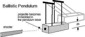
Chronographs have largely superseded ballistic pendulums, though the latter may still be used if one cannot afford a chronograph or there is a danger of damaging one’s chronograph. For instance, inaccurate weapons like derringers or smoothbore pistols loaded with multiple balls might hit the chronograph. Also, if one wants the downrange speed of a rifle bullet, it is possible to fire repeatedly until one hits the pendulum squarely (assuming that the height it rises is recorded automatically, as with an attached pen drawing a line on a sheet of graph paper), but one would not want to put an expensive chronograph downrange where it might get hit. The principle reason that ballistic pendulums are inaccurate is the difficulty of measuring how high the pendulum rises. If the ball does not embed itself squarely in the center of mass, the pendulum may wobble. In 1962, P. O. Ackley overcame this problem by counting the number of oscillations the pendulum makes in a specified time period, like five or ten minutes. While a bit tedious, this is much more accurate. Unfortunately, Ackley pendulums weigh about ten times more than traditional pendulums. This makes them more complicated and expensive than traditional pendulums when testing small arms and wholly impractical when testing cannons. Since I want this website page to be useful to cannoneers as well as riflemen, my Java Applet calculates speed the traditional way. Technical Notes The masses of the ball and the pendulum must be expressed in the same units, though it does not matter what those units are, so one may use pounds instead of kilograms if one prefers. The masses of bullets are typically reported in grains while the scales one might use to weigh the pendulum are calibrated for either pounds or kilograms. Convert grains into kilograms by dividing by 15,432 and grains into pounds by dividing by 7000. The default values are for a 154-grain rifle bullet traveling at 702 m/s (2302 ft/s). The same five-kilogram pendulum will work for a 25-millimeter ball traveling at around 105 m/s (346 ft/s). For more powerful rifles or mortars, one will need either longer cables or a heavier pendulum. A Model 1841 howitzer fires a 4-kilogram shell at 319 m/s, which will lift a 200-kilogram pendulum two meters. When testing such powerful weapons, do some preliminary calculations to determine how large and heavy a pendulum is needed. Building too light could result in a dangerous situation where the pendulum breaks or flips over its support beam. de Mestre, Neville. 1990. The Mathematics of Projectiles in Sports. Cambridge, UK: Cambridge University Press |